Top, Professional and Reliable Manufacturer of Various Machinery – YG Machinery
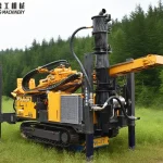
Hydraulic Cable Puller Machine
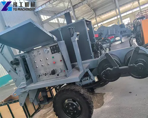
hydraulic cable puller
underground cable pulling machine
On overhead transmission, distribution, substation, and grid-upgrade projects, the risk in stringing is not generally a lack of effort; it is a lack of control. Pull too hard and a conductor, pulling rope, connector, block, or accessory can be damaged; pull too softly or unevenly and the work stalls, loses coordination with the tensioner, and becomes difficult to keep on schedule. A hydraulic cable puller machine exists to apply a controlled pulling force and speed while the line is strung under a matching tension.
What Is a Hydraulic Cable Puller?
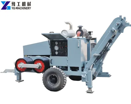
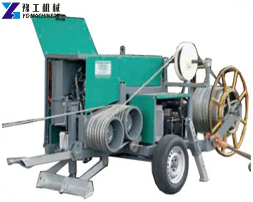
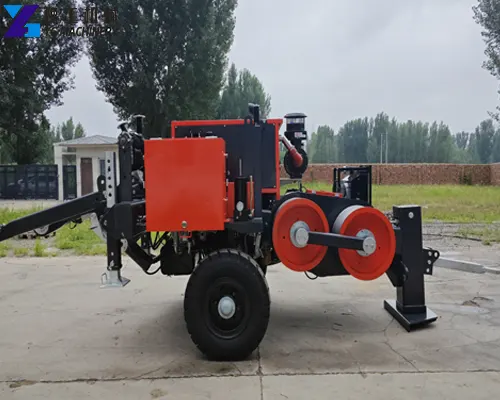
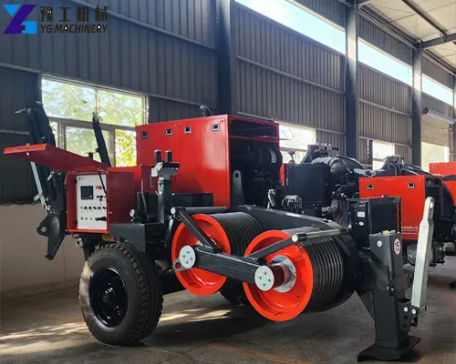
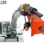
A hydraulic cable puller, also called a hydraulic puller, transmission line puller, wire pulling machine, or power line stringing machine, is a traction device that uses hydraulic power to pull a rope, conductor, cable, or approved assembly along a planned route.
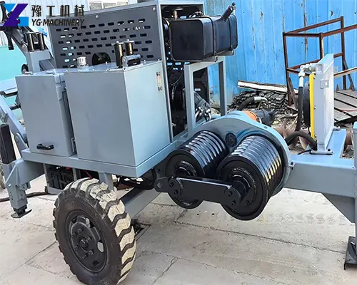
The machine normally applies force through a bullwheel-and-groove system or another approved traction arrangement. The rope passes around or through the traction system, allowing controlled pulling while the operator monitors relevant operating conditions. Machine configuration varies by model and project requirement.
The purpose is not to pull at the highest possible force. The purpose is to maintain pulling conditions within the approved limits of the conductor, cable, rope, blocks, connectors, and construction method.
If you are also interested, please contact us for more product information.
Hydraulic Cable Puller Machine Features and Project Value
Variable hydraulic pulling control → Helps the operator coordinate pulling force and speed with the approved stringing plan, conductor condition, route profile, and crew communication.
Continuous-force rating → Helps buyers choose equipment for sustained work rather than relying only on a peak-force figure that may apply only intermittently.
Bullwheel and groove system → Guides the pulling rope and supports stable traction when the rope diameter, groove arrangement, rope condition, and wrap configuration are correctly matched.
Overpull protection → Helps reduce the risk of exceeding a preset pull limit when it is correctly specified, set, tested, and maintained. It does not eliminate all project risks.
Emergency stop and braking system → Supports controlled stopping in accordance with the approved site safety procedure. Operators must still follow the manufacturer’s manual and project controls.
Diesel-powered hydraulic system → Supports field operation where grid power is unavailable, subject to fuel planning, ventilation, maintenance, environmental requirements, and site restrictions.
Integrated instruments and controls → Help operators observe relevant pulling conditions during work. The exact instruments and monitoring functions are available according to the final configuration.
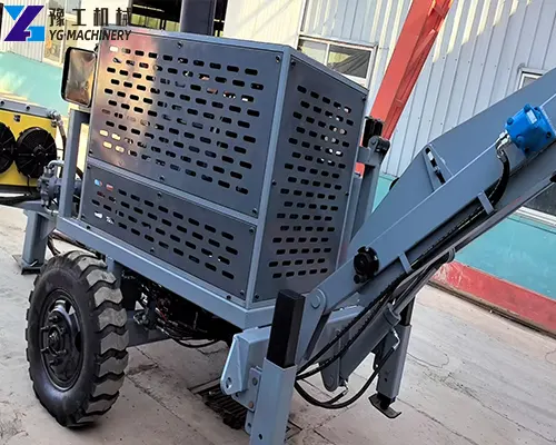
Transportable frame or trailer-mounted layout → Helps contractors plan equipment movement between tower sections or job sites, subject to local transport regulations, machine dimensions, and weight limits.
Optional reel, rope, and accessory compatibility → Allows a project-specific conductor stringing equipment package to be evaluated, subject to engineering confirmation.
How a Hydraulic Cable Puller Machine Fits Into a Stringing Operation
Review approved drawings, conductor or cable data, route profile, crossing plan, and the site safety plan.
Select the puller capacity, rope type, bullwheel or drum arrangement, stringing blocks, connectors, swivels, and other approved accessories.
Inspect the hydraulic cable puller, hydraulic system, pulling rope, brakes, emergency stop, anchoring system, and rated accessories before use.
Position and anchor the machine according to the approved work method, site layout, and manufacturer requirements.
Install the pilot rope and pulling rope through the planned route and stringing blocks.
Set the approved pulling-force limit and speed target according to the engineering plan.
Begin controlled pulling while designated personnel monitor pulling force, speed, communication, route clearance, conductor condition, crossings, and equipment status.
Stop immediately if measured conditions exceed approved limits or if an unsafe condition develops.
Complete conductor sagging, clipping-in, termination, inspection, and documentation according to the approved construction plan.
This overview does not replace a site-specific method statement, risk assessment, manufacturer operating manual, owner specification, local regulation, or trained supervision. Equipment must be operated only by trained personnel under the applicable safety and construction procedures.
High-voltage transmission line stringing. Large conductors and long spans need a puller matched to the approved pulling tension, with a matching tensioner and rope system.
Distribution-line construction and upgrades. Lighter pulling loads and shared traffic areas suit smaller units with clear speed control and safe stopping.
Substation and switchyard connection work. Short, controlled pulls within the yard benefit from precise force setting and compact layouts.
Renewable-energy grid connection projects. Interconnecting wind, solar, or storage plants often involves medium to heavy overhead stringing into the host network.
Railway electrification and traction-power projects. Long, repetitive feeder and contact-system pulls need consistent force and speed over extended routes.
Long-span crossing preparation. River, road, valley, or railway crossings require extra engineering care in force limits, rope, blocks, and coordination.
Underground power cable pulling. Pulling heavy cable into ducts or trenches imposes different limits than overhead work; a configuration sized and approved for underground pulling is required.
Industrial plant and utility infrastructure. On-plant power and distribution runs benefit from compact, controllable pulling units within approved clearances.
Telecommunication or fiber projects. Only when the configuration is correctly sized and approved; fiber pulling is often better served by dedicated, low-tension equipment rather than an overhead conductor puller.
Not every hydraulic puller suits every scenario. High-voltage, multi-conductor, long-span, underground-cable, and fiber projects require application-specific selection and compliance review.
How to Choose the Right Hydraulic Cable Puller?
Start with the approved maximum pulling tension, not a general tonnage preference — the engineering plan defines the real force requirement.
Compare maximum force with continuous force so the machine is selected for sustained work, not only a peak number.
Confirm conductor/cable type, diameter, weight, construction, and allowable pulling tension.
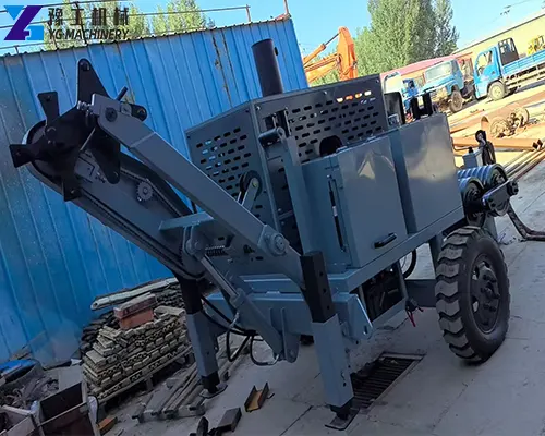
hydraulic cable puller for overhead transmission line stringing
Frequently Asked Questions About Hydraulic Cable Puller Machine
Q1: What pulling force do I need for my project?
A1: The required pulling force should be determined from the approved stringing or cable-pulling calculation—not only from the voltage level or a general tonnage preference. Please provide the conductor or cable type, diameter, unit weight, allowable pulling tension, route length, maximum span, elevation changes, crossings, bends, and the number of conductors. These details help determine the appropriate maximum and continuous pulling-force range.
Q2: What is the difference between maximum and continuous pulling force?
A2: Maximum pulling force is the highest traction a hydraulic cable puller machine can produce under specified, often intermittent, conditions. Continuous pulling force is the traction level the machine can sustain during ongoing work under its stated duty conditions. For long-distance conductor stringing, buyers should evaluate the continuous rating rather than choosing a machine only by its peak pulling-force figure.
Q3: Should I choose a hydraulic puller, a hydraulic tensioner, or a puller-tensioner?
A3: A hydraulic puller provides controlled forward traction to pull a pilot rope, pulling rope, conductor, or approved cable assembly. A hydraulic tensioner provides controlled back-tension while the conductor is paid out from its reel. For many overhead transmission projects, both functions are needed as part of a coordinated stringing system. Whether to use separate equipment or a combined puller-tensioner depends on the conductor arrangement, project specification, construction method, and required control level.
Q4: Can this hydraulic cable puller machine handle my conductor, cable, rope, and connector size?
A4: Compatibility must be checked before ordering. Confirm the conductor or cable diameter, pulling-rope diameter and breaking strength, connector outside diameter, required through-connector clearance, bullwheel diameter, groove number, and groove size. A machine with enough pulling force may still be unsuitable if the rope, connector, bullwheel, or accessory dimensions do not match the final configuration.
Q5: Can I use the machine for underground power cable or fiber-optic cable installation?
A5: It may be possible, but suitability depends on the exact cable and route. Underground power-cable pulling requires confirmation of allowable pulling tension, bend radius, duct condition, cable pulling eye, lubrication method, route length, bends, and required monitoring. Fiber-optic cable normally has lower allowable pulling tension and strict bend-radius limits, so a heavy-duty transmission puller should not be selected without a project-specific review.